Design and Analysis of a Cold Gas Rocket Engine
Abstract
This project involves the comprehensive mathematical modeling, design, and transient performance analysis of a simplified cold gas rocket engine system.
Documentation:
View full technical report (Google Drive)
System Overview
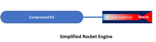
The engine model consists of three primary components designed to simulate high-performance propulsion:
- Pressurized Tank: A 0.5 m³ cold gas tank pressurized with air to an initial pressure of 200 bar.
- Combustor (Heat Addition Duct): A one-dimensional duct that simulates a combustion chamber by adding thermal energy, raising the gas temperature to a maximum of 2200 K.
- Convergent–Divergent (CD) Nozzle: A fixed-geometry nozzle designed at a 100-bar reference condition to optimize mass flow rate and expansion behavior.
Design Flowchart
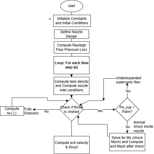
The following flowchart illustrates the overall design and analysis workflow:
Methodology and Physical Modeling
The project utilizes an unsteady flow model based on the fundamental conservation of mass and energy. Key theoretical frameworks include:
- Isentropic Blowdown
- Rayleigh Flow
- Shock Logic
Key Performance Results
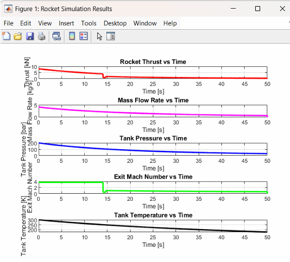
- Thrust: ≈ 8.5 kN
- Mass flow: ≈ 4 kg/s
- Stagnation pressure loss: 4.8%
- Shock transition: ≈ 14 s
- Combustor diameter: 0.0861 m
Governing Equations
1. Isentropic Tank Blowdown
Pressure update:
\[P_{\text{tank}}^{n+1} = P_{\text{tank}}^{n} \left( \frac{\rho_{\text{new}}}{\rho_{\text{old}}} \right)^{\gamma}\]Temperature update:
\[T_{\text{tank}}^{n+1} = T_{\text{tank}}^{n} \left( \frac{\rho_{\text{new}}}{\rho_{\text{old}}} \right)^{\gamma - 1}\]2. Nozzle Mass Flow Rate (Choked Flow)
\[\dot{m} = P_0 A^* \sqrt{ \frac{\gamma}{R T_0} \left( \frac{2}{\gamma + 1} \right)^{\frac{\gamma + 1}{\gamma - 1}} }\]where:
- \(P_0\) stagnation pressure
- \(T_0\) stagnation temperature
- \(A^*\) throat area
3. Rayleigh Flow (Heat Addition)
\[\frac{P_{02}}{P_{01}} = \frac{1 + \gamma M_2^2}{1 + \gamma M_1^2} \left( \frac{1 + \frac{\gamma - 1}{2} M_1^2} {1 + \frac{\gamma - 1}{2} M_2^2} \right)^{\frac{\gamma - 1}{\gamma}}\]4. Normal Shock and Exit Conditions
\[P_{\text{sup}} \left( 1 + \frac{\gamma + 1}{2\gamma}(M_s^2 - 1) \right) = P_{\text{atm}}\] \[M_e = \sqrt{ \frac{\gamma M_s^2 - \frac{2}{\gamma - 1}} {1 + \frac{2}{\gamma - 1} M_s^2} }\]5. Propulsion Performance
Thrust:
\[F = \dot{m} V_e + (P_e - P_{\text{atm}}) A_e\]Exit velocity:
\[V_e = M_e \sqrt{\gamma R T_e}\]Exit temperature:
\[T_e = \frac{T_0} {1 + \frac{\gamma - 1}{2} M_e^2}\]6. Combustor Geometry Design
Low inlet Mach number:
\[M_c = 0.1\]Area:
\[A_c = \frac{\dot{m} \sqrt{T_0}}{P_0} \sqrt{\frac{R}{\gamma}} \frac{1}{M_c} \left( 1 + \frac{\gamma - 1}{2} M_c^2 \right)^{\frac{\gamma + 1}{2(\gamma - 1)}}\]Diameter:
\[D_c = \sqrt{\frac{4 A_c}{\pi}}\]Nozzle Design
The nozzle was designed as a converging–diverging (De Laval) nozzle to ensure choked flow at the throat and supersonic expansion at the exit.
MATLAB Simulation
Conclusion
This project successfully demonstrated the complete design and analysis cycle of a cold gas rocket engine. The analytical model was validated through simulation and matched expected theoretical behavior.
References
- Sutton & Biblarz — Rocket Propulsion Elements
- Humble, Henry & Larson — Space Propulsion Analysis and Design
- NASA Glenn Research Center — Cold Gas Propulsion Systems